

How to Avoid Electrical Hazards with Air Logic
Category:
![]() BY KENNETH J. KORANE ON NOVEMBER 06, 2012
BY KENNETH J. KORANE ON NOVEMBER 06, 2012
|
Key Points:
• Air logic functions like relays, switches, and counters, but uses compressed air instead of electricity. • Air-logic controls are preferred in wet or dusty conditions because they pose little danger of electrical explosion or shock. Electrical and electronic devices such as logic circuits, programmable controllers, and PCs normally control fluid-power and fluid-handling circuits. Such systems can also operate with “air logic,” controls that function like relays, switches, time delays, and counters. However, while the circuitry is similar, compressed air is the control medium instead of electric current. Air-logic controls are often preferred in wet or dusty environments because they pose practically no danger of explosion or electrical shock. Likewise, air controls cannot ignite explosive or flammable gases and vapors. And they’re rugged. Water can splash on the controls without affecting operations, and they tolerate dust and dirt. Air logic can also be used on machines with fluid-power components but no electrical supply. Air logic does have disadvantages. Most common is a lack of understanding among maintenance personnel on how to read schematics and troubleshoot problems. Also, air logic with long control lines responds noticeably slower than electronics. That’s because control lines longer than 10 to 15 ft fill and exhaust slowly compared to near-instantaneous electrical signals. In addition, it takes a high-quality, filtered air supply to ensure long life. Air-logic controls are basically miniature three and four-way air valves. Components include the familiar and, or, not, yes, and flip-flop elements, as well as timers and delays. Valves provide on or off functions like relays or switches, and also exhaust the spent signals. Here’s how one OEM uses air logic to its advantage. 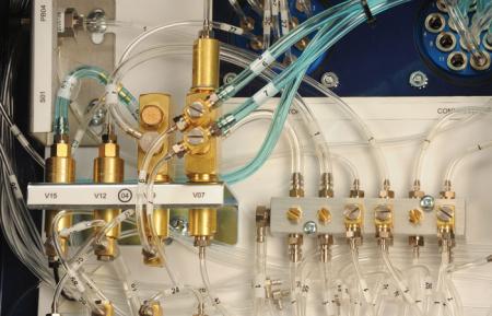 Air logic controls for composites manufacturing rely on miniature valves, manifolds and other components from Clippard Instrument Laboratory. Air logic controls for composites manufacturing rely on miniature valves, manifolds and other components from Clippard Instrument Laboratory.Molding composites “Traditionally, fiberglass and composite parts have been made in an open-molding process,” explains Jeff Austad, vice president of distribution and specialty sales for Magnum Venus Plastech (MVP), a Clearwater, Fla.-based manufacturer of pumping and meter-mix equipment used to make composites. Typically, workers spray a gel-coated mold with a mixture of catalyzed resin and glass fibers, then the part is oven cured, cooled, and removed from the reusable mold. Over the last couple of decades, regulations have gotten a lot tougher regarding worker exposure to hazardous materials such as styrene, as well as emissions of noxious fumes into the environment, says Austad. Safety concerns have grown, too. The resins are flammable, so minimizing fire hazards and, in turn, insurance costs, are also taking center stage. That has spurred a move to closed-mold processing. As the name implies, instead of spraying material to make a part, the resin and other constituents are injected into a closed and sealed mold. Versions of this process include resin-transfer molding (RTM), light RTM (vacuum-assisted), vacuum-infusion molding, and closed-cavity bag molding. Closed molding, first of all, lowers emissions, says Austad. It results in a much cleaner work environment and reduces the need for protective clothing, respirators, and expensive ventilation systems. The automated process also reduces manual labor and improves part quality dramatically. “Open-molded parts might vary by 15 to 20%, depending on the skill of the operator, and that can generate considerable waste. Closed molding takes that out of the equation by injecting the same amount of resin into the mold every time, resulting in minimal trim waste and less finishing after the part is made,” says Austad. Closed molding better controls component thickness and produces a higher-quality part that’s smooth and shiny on both sides, he adds. On open-molded parts, one side usually has a rough, unfinished surface. But closed molding requires precisely controlled metering and mixing of the resin and catalyst, as well as the amount of catalyzed resin injected into the mold. While it’s possible to use PLC-based controls with flowmeters, the resins are flammable so that would require explosionproof electrical systems, and they are quite expensive. Instead, MVP’s engineers opted for all-pneumatic controls using valves and logic components from Cincinnati-based Clippard Instrument Laboratory. 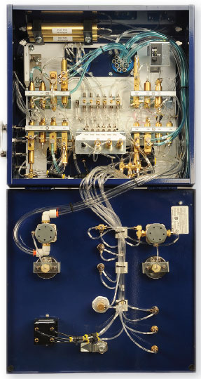 Pneumatic circuits precisely control resin-injection rate and pressure. Pneumatic circuits precisely control resin-injection rate and pressure. Air-logic controls The pneumatic controls perform three major tasks, explains Tim De- Luca, vice president of MVPs RTM Div. The first is to repetitively inject the same shot size into the cavity every time, eliminating guess work on the part of the operator. Once userdesignated injection parameters are reached, a counter circuit shuts off injection. Second, the controls manage injection pressure and prevent overpressure conditions which could blow out clamps or resin seals, says DeLuca. A pneumatic switch —called a PV switch — can be mounted in the mold to sense resin pressure for closed-loop control. “Customers who require higher precision, say for aircraft or automobile parts held to tight tolerances, are more likely to want this option,” notes Austad. Overpressure can result in parts with inconsistent thickness. So sensing pressure lets the controller slow the pump, shut off the injector, or both. The last, and perhaps most important, function is the control interlock. At no time can operators accidently push the wrong button and botch the process. During certain cycles, some functions are locked out and not usable. This prevents costly mistakes, says DeLuca. Precise pumping The air motor driving the pumps uses line-pressure pilot valves, which shift a four-way valve spool to reverse the pump. Keys for quickly reversing the pump are a light spring load on the pilots and large exhaust ports on the valve. Also, the air cylinder has a 2-in. stroke that minimizes the volume of air that must exhaust when the pump reverses. Older versions used 4 and 6-in. stroke cylinders, which take longer to exhaust due to the greater volume of compressed air. All this adds up to faster pumping with quick changes in direction. Low-friction seals, along with a balanced power ratio pneumatic drive, help ensure uniform material delivery at high and low flow rates, says DeLuca. 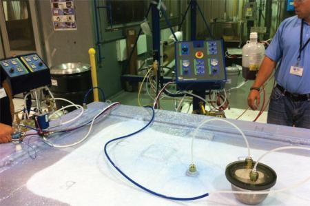 Air logic minimizes fire and explosion hazards in composites molding operations. Air logic minimizes fire and explosion hazards in composites molding operations. Innovative design And MVP wanted the controls to work with a variety of its equipment. Looking to build greater versatility and functionality into the controls, engineers from MVP and Clippard distributor AOP Technologies, Auburn, Wash., made key improvements, notes DeLuca. “We changed all the control lines to /-in. OD to get faster reaction times on the circuits. All of the valves that actually control outside sources were upsized to allow for more flow so that we could use longer trigger lines outside the box,” he says. 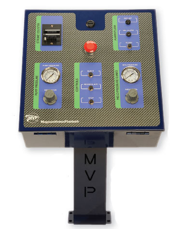 MVP's Innovator II controls are shipped worldwide and built for durability and low maintenance. MVP's Innovator II controls are shipped worldwide and built for durability and low maintenance. “Using stand-alone brass valves from Clippard, we arranged valves into ‘banks.’ Four of the valve banks are essentially complete circuits, to ease troubleshooting. The fifth is an overall control circuit with flow controls for system tuning. Some redundancies were removed and common valves were used when possible to reduce the number of different parts,” notes DeLuca. Another important feature: the solvent flush cannot back up into the air supply and ruin the entire controller, thanks to a ‘sacrificial’ blocking valve added to the circuit. In addition to converting to inch-size fittings and tubing, the plumbing was streamlined and secured with clips for a better appearance and easier troubleshooting. Also, all 70+ lines and valves are labeled for identification versus the schematic. Finally, the control box can handle remote-control pendant operation, multiple feedback devices, and different styles of mix-meter equipment. Ensuring reliability “Because of the proven reliability and durability of Clippard air-logic valves, we expect these systems to be trouble-free for many years,” adds DeLuca. “Other than cleaning the air filter, no maintenance is required.” |
|
Components: MAV-3 Stem Valve, 15002-6 Fitting, 15080 Muffler, FV-3P Stem Valve, MPA-3 Actuator, MAV-4D Stem Valve, 11782-4 Connector, 11755 Screw Plug, 15002-1 Fitting, 11782-5 Fitting Original article with Machine Design |


