

Gas Mass Flow Controllers - An Overview of Technologies
Category:
Many medical, analytical, and industrial equipment and device manufacturers utilize mass flow controllers to measure and control the flow of gases. This article explores several mass flow controller technologies commonly used to control the flow of gases, along with considerations to evaluate to correctly specify a mass flow controller for your gas flow control application.
A mass flow controller (MFC) is a device used to measure and control the flow of liquids and gases. For this article, we’ll be focusing our discussion on mass flow technologies used in the flow control of gases for many medical, analytical, and industrial applications, such as sparger gas control in bioreactors, gas blending for medical processes, gas sampling for analytical equipment, gas mixing for plasma cutting and welding, and process gas flow for semiconductor manufacturing.
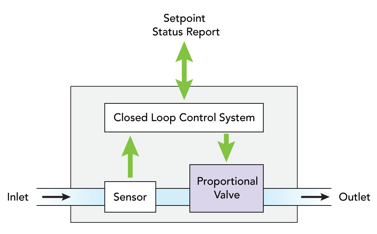
All mass flow controllers have several common components (as shown in the figure to the right)—an inlet port, an outlet port, a mass flow sensor, a proportional control valve, and a closed loop control system. The control system compares a flow value measured by the mass flow sensor to an operator-provided input signal (e.g., external circuit or computer). The controller then adjusts the proportional valve accordingly to achieve the desired flow.
What most significantly differentiates
mass flow controllers marketed today
is the mass flow sensor technology
utilized in the device.
What most significantly differentiates gas mass flow controllers marketed today is the mass flow sensor technology utilized in the device. The sensor technology determines many of the more significant considerations to evaluate when evaluating a mass flow controller for an application. Several common mass flow sensor technologies include Coriolis, thermal and differential-pressure.
Coriolis Mass Flow
The Coriolis principle is very basic but highly effective. It involves a tube that is energized by a fixed vibration. When a fluid passes through the tube, the mass flow momentum changes the vibration of the tube, which is a phase shift. From the phase shift, a linear output is obtained that is proportional to the flow. The Coriolis method for measuring mass flow is also independent of the type of material in the tube and can be applied to any gas or liquid. In other words, it can be used to measure the mass flow of any gas or liquid with no knowledge of the media’s identity or fluid properties. These sensors are exceptionally accurate, repeatable, and can be used with a wide variety and mixes of gases and liquids without re-calibration. However, this technology is relatively expensive, can have high pressure drops across the device, and is susceptible to errors due to sources of vibration.
Thermal Mass Flow
Thermal mass flow sensors operate either by introducing a known amount of heat into the flowing stream and measuring an associated temperature change or by maintaining a probe at a constant temperature and measuring the energy required to do so. Unlike the Coriolis technology, thermal mass flow controllers require calibration for different gases since the thermal properties of the gases differ.
The first thermal mass flow technology we’ll evaluate is the capillary tube type of thermal mass flow meter, where the flow enters the flow body and splits into two internal flow paths. The gas flowing through the main flow path inside the body travels through a laminar flow element, creating a pressure drop that forces a small fraction of the total mass flow through an adjacent heated capillary sensor tube. This sensor tube has a small diameter, relatively long length, and measures the mass flow rate by means of the heat capacity of the gas carrying heat from an upstream sensor to a downstream sensor winding, both on the outside of the tube. The difference measured between the two resistive sensors provides the measurement of the mass flow rate through the sensor tube and, thereby, the total mass flow rate through the device.
These sensors are also highly accurate and capable of higher industrial-type flow ranges and inlet pressures. Due to the resistive temperature sensing involved in this technology, response times to pressure changes for these devices are slower, making them more suitable for applications that require the maintenance of a steady process flow.
MEMs is another thermal mass flow sensor technology that utilizes a MEMs mass flow chip consisting of a heating element and two highly sensitive temperature sensors. The MEMs chip is located directly within the flow channel of the device. As the gas flows across the inserted chip, the temperature differential measured across the sensors is directly converted into a mass flow measurement. This MEMs chip technology is typically limited to lower flow and inlet pressure applications. However, it is very accurate and responds to set point changes within milliseconds, lending itself to lower flow applications requiring precision control and quick response times to commanded changes in flow.
Differential-Pressure Mass Flow
Finally, we’ll review mass flow controllers that utilize differential pressure technologies to measure flow rates. Unique to differential pressure mass flow controllers is that additional pressure and temperature sensors have to be incorporated into the device, or density correction factors assumed, to control mass flow. Differential pressure sensing provides data that is only relatable to volumetric flow, a measure of the volume of media that flows through an instrument per unit time, rather than mass flow, which is a measure of volumetric flow corrected to standard conditions. Hence flow sensing devices that don’t directly measure mass flow, like differential pressure technologies, require additional temperature and pressure-dependent density correction factors to convert to a standardized mass flow rate.
Laminar DP mass flow controllers use the pressure drop created within a laminar flow element (LFE) to measure the mass flow rate of a fluid. To do this, an LFE converts turbulent flow into laminar flow by separating it into an array of thin, parallel channels. The pressure drop across the channel is measured using a differential pressure sensor. The pressure drop is then related to a volumetric flow rate, which can then be converted to a standardized mass flow rate using temperature and pressure-dependent density correction factors. Laminar DP controllers have quick response times and can be highly accurate depending on the accuracy of the density correction factors. Laminar flow measurement depends on accurate data for how a gas reacts with varying pressure and temperature, which means knowing the exact gas composition is required for accurate measurement. And due to the geometry of the thin parallel channels, these devices are susceptible to clogging or condensation, which can also affect the system’s accuracy.
A Venturi flow meter is a type of differential pressure flow meter that generates a flow measurement by measuring the pressure difference at two locations in a pipe. This pressure difference is created by constricting the diameter of the pipe, which causes an increase in flow velocity and a corresponding pressure drop. Through these changes in the fluid flow, the volumetric flow rate can be determined, then further converted to a mass flow rate. These devices provide very quick response to flow command changes, but typically at the expense of accuracy and repeatability.
Specifying a mass flow controller involves careful consideration of the technologies that will meet the flow control performance and operational features required of your application. Primary performance considerations to evaluate include flow range, response time, accuracy, resolution, and all potential gas condition variables of the application—including needs for pre-calibration. Several operational features to consider include signal/command control options (e.g., 0-5V, 0-10V, and 4-20mA analog; 3.3V/5.0V TTL, RS-232, and RS-485 serial), needs for output displays or I/O, and availability of user-programmable or pre-programmed gas calibrations. Finally, the budget should also be a consideration as the choices made can significantly impact expenses.
By Doug Robertson • Director of Research • Clippard
|
Related Products |
||||
Cordis Electronic Pressure Controller |
||||


