

Cordis CPC Electronic Pressure Controller Troubleshooting Guide
Category:
If the blue LED is not illuminated:
- The micro-controller has failed
Possible causes of micro-controller failure:
- High frequency AC noise
- Electro-Static Discharge (ESD)
- A signal greater than 3.3 VDC on the serial communication lines (Pin 5 RX
and Pin 6 TX).
- A signal greater than 3.3 VDC could have come from using RS-232 cable which generates 5 VDC to the micro-controller serial inputs.
If red LED is not illuminated:
- Verify 15-24 VDC power and ground are properly hooked up.
- If 15-24 VDC power and ground are accurately installed the device needs
returned to the factory for evaluation.
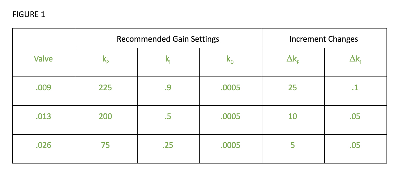
PID Observations & Solutions:
These scenarios are dependent on downstream volumes and valve orifice size.
Suggested PID increments per valve size can be found in figure 1.
If proportional setting is too low, the output pressure will hunt around the desired set point within the specified tolerance; taking a long time to settle if it ever does.
- Increase the proportional value until the valves ring at a high frequency for
a short period, then lower to the point that the output settles quickly but
ringing is eliminated.
If proportional setting is too high, the valves will ring at a high frequency
for a short period of time when command signals are varied.
- Lower the proportional value until the ringing is eliminated.
If integral is too low, the output pressure could fall outside of the
specification.
It will also become less sensitive to changes in command, and when exhausting to 0% of command, may close the exhaust valve before venting off all of the pressure.
- Increase integral until the output pressure gets to pressure at the desired
speed without spiking pressures/overshooting.
If integral is too high, a change in command will result in an overshoot of set point. Testing has shown as high as 2% spike in pressure when "integral" is too high.
- Begin lowering integral value until overshoot/pressure spikes are
eliminated.
If a command is given to the Cordis device and there is no response:
Confirm the inlet pressure is sufficient. To determine what these pressures should be, refer to the Installation Instructions Guide.
Verify that the PID settings are not set too low.
If PID values are acceptable, use a voltmeter to check the voltages on the inlet valve connector. With a command and adequate supply pressure, there should be a 11.7 VDC on 1 Pin and 0.2 VDC on the other. If these values are adequate and there is still no pressure output, the valve is faulty or the valve wires were not crimped properly.
If the Cordis device is at pressure, but when the command is lowered,
the output pressure does not exhaust:
Verify the integral setting is not too low.
If the PID values are acceptable use a voltmeter to check the voltages on the exhaust valve connector. When the command signal is lower than the monitor signal or output pressure, there should be a 11.7 VDC on 1 pin and 0.2 VDC on the other. If this is the case, the valve is faulty or the valve wires were not crimped properly.
What happens if the filtration is wrong?
If there is insufficient filtering, sealant, thread tape, metal shaving from piping/plumbing it could migrate to the inlet valve causing the supply pressure to leak past the seat and nozzle to the process side. This will cause a slow loping or high frequency compensation from the inlet valve resulting in premature wear and ultimately failure
If the filtration is too constrictive and restricing the flow too much, this could hurt the performance of the Cordis device by not allowing the valves to be the limiting factor of the control system.
What happens if the customer uses the wrong sealant?
The result of using sealant such as thread tape or pipe dope is that it inherently will fragment or flake once it has solidified and can easily migrate into the pneumatic system. If this occurs and proper filtration is not used, it could result in valve contamination.
What happens if the customer uses the wrong media?
If a media that is not a clean, dry, non-corrosive gas is used through the Cordis, damage to the pressure sensor could occur. This damage to the sensor could result in the element being over-pressurized due to hydrostatic pressure of liquid or the element's output value shifting due to corrosion building on the sense element.
What happens if the customer uses the wrong USB to TTL cord type (5 VDC)?
If a 5 VDC USB to TTL cable is used which would apply 5 volts to pins 5 and 6 of the card assemblies, and pins 2 and 7 on the housed assemblies, the micro-controller could fail due to exceeding its 3.3 VDC rating.


