

The Building Blocks of Air Circuits
Category:
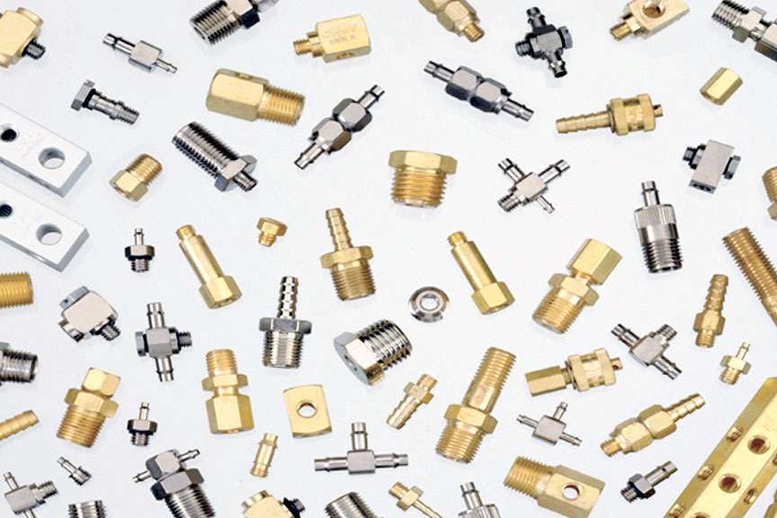
Unless all your pneumatic connections are brazed or soldered, fittings are a part of all your system designs. A huge variety of fitting configurations exist, and in many different materials.
The most leak-resistant joints for pneumatic lines are those that have been soldered or brazed. However, two big drawbacks to these ultra-reliable joints are installation cost and extreme difficulty if a joint has to be replaced at a later time.
For these reasons, many different types of fittings have found favor in pneumatic systems because they are much less labor-intensive at installation, and lines can be removed and replaced many times with little effort.
RELATED
But what about leakage? As long as the appropriate fitting is chosen for the application, there's no reason why a connection using threaded fittings shouldn't be just as leak-tight as a brazed or soldered joint. Just as people untrained in brazing or soldering should not be making these types of connections, people untrained in working with pneumatics should not be installing fittings. In fact, the International Fluid Power Society offers certification for working with connectors and conductors.
Material—An Important Consideration
The type of material making up the fitting is a primary characteristic determining the success of the application. Using a material that will be attacked by a hostile environment, cannot contain the pneumatic pressure, or doesn't stand up to physical stresses transmitted to the fitting will likely lead to a catastrophic failure. On the other hand, specifying a material that far exceeds the parameters of the application wastes money.
Carbon steel is strong, with a high resistance to heat. An alloy primarily of iron and carbon, steel is typically alloyed with other metals to improve its corrosion resistance. In addition, steels used for pneumatic fittings often have coatings or platings that offer greater greater corrosion resistance than the steel itself.
Strong, durable, and corrosion-resistant, with high temperature ductility and good conductivity, brass is an alloy of copper and zinc. It is the most common metal for smaller compression and threaded fitting typical of pneumatic systems because of its machinability and good mechanical properties.
Aluminum is lightweight and corrosion-resistant, but because of its low strength in its pure state, aluminum is usually alloyed with zinc, copper, silicon, manganese, and/or other metals to improve its strength and hardness.
Exhibiting high strength and high corrosion resistance, stainless steels contain less carbon than an alloy of plain steels and are alloyed of steel that contains more than 10% chromium. They have the strength and durability of steel while also providing excellent corrosion resistance, albeit typically at a higher cost.
Moving to plastics, polypropylene is a thermoplastic widely used for pneumatic fittings because of its price, broad compatibility, and relatively high strength. It exhibits good bi-axial strength and yield-elongation properties and can be used in exposed applications because of its resistance to UV, weathering, and ozone.
Composites consist of different materials merged together so that the fitting exhibits the favorable properties of both materials. They also exhibit low electrical and thermal conductivity.
Putting It All Together
Poor plumbing practices can cripple a pneumatic circuit even if it was designed with the best engineering practices and assembled with the most up-to-date components. Undersized lines, elbows instead of bends, incorrect component placement, and long piping runs are just a few of the limitations that can restrict compressed air flow.
Other problems, such as using tapered pipe threads or lines with thin walls, can make a circuit a maintenance nightmare that requires daily attention. Fortunately, numerous publications can assist in specifying correct line size and conductor thickness to give low pressure drop and safe working-pressure limits.
An important characteristic that often is overlooked is the length and size of lines between the valves and actuators. Piping between the valve and actuator should be as short as possible and of the minimum diameter to carry the required flow. The reason for this is that all the air in the pipes between the actuator and valve is wasted every cycle. These runs must be filled to make the device move, but the air it takes to fill them does no work. During each cycle, air in the actuator lines exhausts to atmosphere without helping cycle time or force. For this reason, always mount the valve close to the actuator ports.

Original Article, February 2016
By Alan Hitchcox


