
1030 Non-Contact Gap Sensor
Category:
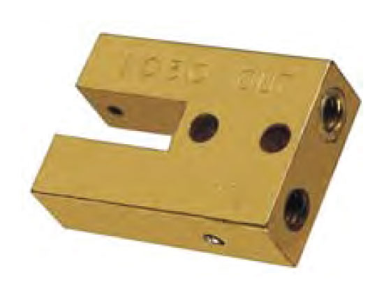   |
Clippard's 1030 Non-Contact Gap Sensor will sense any flat or round object with a 1/32" minimum radius. The sensor produces a positive signal when no object is present, and a negative signal when an object interruts its sensing system. 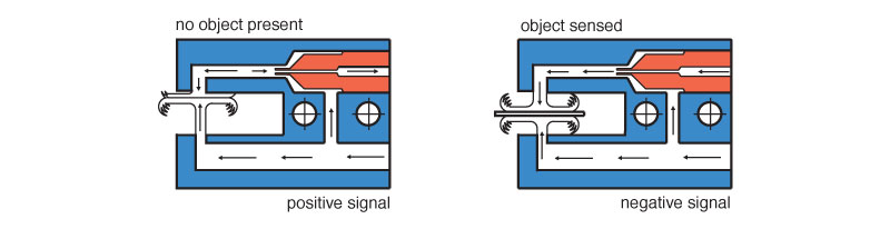 Medium: Air
|
|
|
|
Design Tips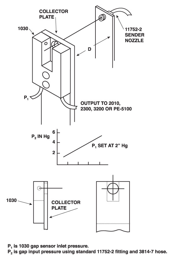
Non-contact sensing of distances up to 4 inches may be accomplished using a standard 1030 gap sensor and the readily constructed installation shown at left.
Operation of the gap sensor is more consistently stable when the 1030 is mounted on a plate with a 1/4 inch hole to act as a "collector" of the stream of air across the gap from the 11752-2 sender nozzle. This "plate" has been found to minimize interference from ambient air currents and to reduce turbulence of the air stream where it reaches the primary sending gap. It should be noted that this assembly reverses the sensed output when compared to using the 1030 by itself. The stream of air coming from the sender nozzle causes the 1030 to react as if an object was placed in the sensing gap. An object across the area defined by D eliminates the interference as sensed by the 1030 and the 1030 output becomes a positive pressure. This design tip is suggested as a possible solution to a sensing/control problem. It has proven to be practical and reliable in laboratory set ups, however, it may not be so in all applications. The user is advised to carefully test this set up under actual working conditions in order to determine its suitability in their specific application.
|
|