

How Stepper Motors Provide Precision Control
Category:
Stepper motors are used in a variety of applications to provide a means for tightly controlled motion. But what is a stepper motor, and how does it work? This paper will discuss bipolar motors in detail, explaining what they are and how they work, and providing examples of how they're used with different types of proportional valves to provide precise control.
What is a Stepper Motor?
Stepper motors are brushless DC motors that rotate in steps electronically set by a controller or drive, which provides the necessary current through electromagnets that are arranged in a ring as part of the stator assembly (the stationary portion of the motor). Stepper motors are ideal for applications that require speed and position control, especially at low speeds such as in automation, motion systems, and 3D printers. Due to their internal design which minimizes mechanical and electrical "delays" that occur in other motors, stepper motors have remarkable stopping accuracy and responsiveness. Often, this makes stepper motors an ideal choice for synchronous and high precision operations.
How do Stepper Motors Work?
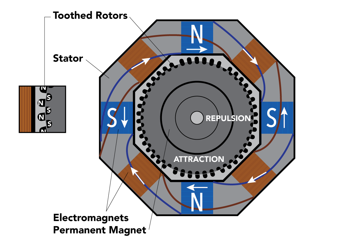
Figure 1. Diagram of a Stepper Motor
At the core of a stepper motor is a permanent magnet and shaft down the center of two or more toothed rotors. These rotors have different polarities because of the enclosed magnet and are offset from one another to allow themselves to be better drawn to the electro-magnetized teeth that cover the internal surface of the stator. The stator has fewer teeth than each rotor to ensure full alignment can only occur in sections (stator plates) along coil pairs. Energizing and de-energizing in-turn coil pairs causes the shaft to rotate a full step due to the attraction and repulsion of the magnetized teeth.
How to Calculate Stepper Motor Steps

Figure 2. Step Angle Calculation
A step angle is the angle of rotation traveled in a single step. This can be calculated one of two ways—either by dividing the motor's full 360 degrees by the number of steps the motor takes to complete one revolution, or by dividing the motor's full 360 degrees by two times the number of rotor teeth times the number of stator phases (Fig. 2).
Microstepping
Simultaneously manipulating the currents through multiple coil pairs reduces the overall travel/rotation by attracting the teeth in two directions instead of just one, creating new half, quarter, eighth, or one-sixteenth step set transitions known as microsteps. Microstepping provides better resolution and reduces resonance/vibrations, but also decreases torque and can be detrimental to bare accuracy.
Stepper Motor Drives and Control
Energizing the coils of a stepper motor in the right sequence to achieve a single step is a complex task. As such, the actual control of the motor coils is typically achieved using a driver. There are two types of stepper motor drives—constant voltage (L/R drive) and constant current (chopper drive). L/R drives are primarily limited to low-speed applications, therefore, we will focus on chopper drives. If you're interested in learning more, this article provides a good overview of the difference between an L/R drive and a chopper drive.

Figure 3. Relationship Between Current Rise and Inductance
Drivers simplify the operation of a stepper motor by interpreting a digital step and direction signal from a controller and energizing the motor coils accordingly. All electronics are governed by Ohm's Law and the relationship between current rise and inductance (Fig. 3). With stepper motors, the motor's design (in regard to its coils) prevents current from increasing quickly during pulses (command signals), which means the current can never reach its peak value without very high voltage. This is a problem because without sufficient current, the torque will be low, especially at high motor speeds. To combat this, chopper drives perform what is known as Pulse Width Modulation (PWM).
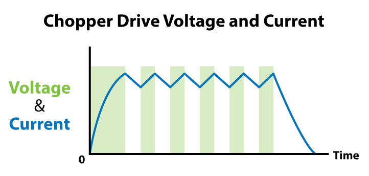
Figure 4. Chopper Drive Voltage and Current
Pulse Width Modulation (PWM)
Pulse Width Modulation (PWM) involves turning the output voltage to the motor on and off very quickly at each step. This provides very high voltage to the motor's coils (usually 8 times more than the motor's nominal voltage) which causes the current to rise rapidly and be higher than it would be otherwise. This on-and-off action typically occurs at a frequency of 20 kHz or higher, but the voltage "on-time" is influenced by the coil's impedance and motor speed—thus at higher speeds the voltage is on longer (larger pulse widths) to produce an average current at the correct level (Fig. 3).
Stepper Motor Chopper Drives
Stepper motor chopper drives are regulated by a current-sensing resistor placed in series with each coil. The resistor develops voltage across itself which is then monitored by a comparator. When this voltage reaches a preset reference voltage, it is "chopped" (turned off) until the next pulse occurs. This enables the average current to be stable despite any variations in the power supply voltage and increases efficiency by ensuring the shortest possible intervals between current peaks and valleys.
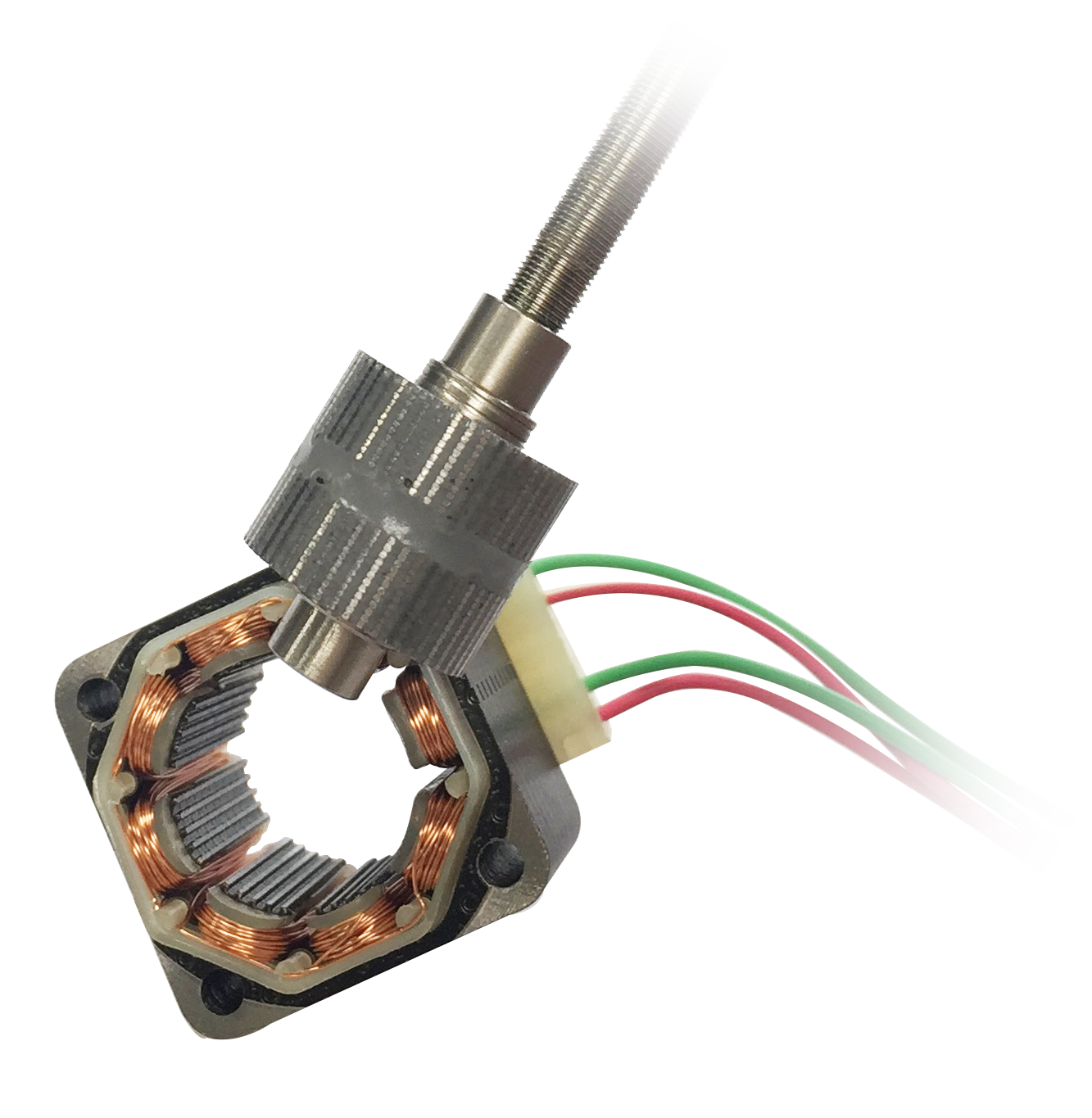
Stepper Motor Linear Actuators
A stepper motor can have a threaded shaft attached to its rotating core which can then be used to push or pull a nut placed upon it, moving it axially. The pitch of the thread controls how far the nut can move per step, with the resolution/precision dictated in part by the step angle utilized by the stepper motor (full, half, quarter, etc.). Like most linear systems, a stepper driven linear actuator can be susceptible to backlash. Backlash is caused by "slop" or "play" between the threads on the nut and the threads on the lead screw. Having clearance between threads results in a dead zone when the direction of travel is changed. When reversing direction, there will be no movement in the linear actuator until the clearance between threads is removed (the threads make contact again). For this reason, it is recommended that the threads have as tight a tolerance as possible. Designers must work to balance the backlash and the friction that is introduced when tolerances are tightened.
Stepper-Controlled Clippard Proportional Valves
Clippard's SCPV Series uses a stepper motor to control the distance between a needle and a valve seat. Precise proportional flow is achieved by adjusting the position of the needle. Due to the type of stepper motor linear actuator used on the SCPV, it is not recommended to implement microstepping beyond a half step. Full stepping is recommended and equates to 0.001" of linear travel which will result in a flow resolution of 0.7 slpm air.
Although stepper motors may seem complicated compared to a standard DC motor, as we have shown, their basic operation is actually quite simple. Their unique internal design enables remarkable stopping accuracy and responsiveness, making stepper motors an ideal choice for use in a wide variety of applications requiring precise control.
If you have questions about stepper motors or want to learn more about using a stepper-controlled proportional flow control valve in your application, locate your nearest Clippard distributor or contact Clippard today.
|
Related Products |
||||
|
SCPV Series Proportional Valve 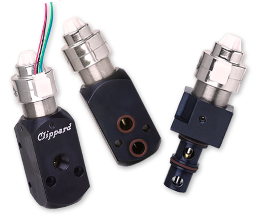 |
||||


