

Simplified Pneumatic Symbols
Category:
The components needed to manufacture and construct pneumatic logic control circuits are readily available, reliable and have been proven in countless applications. The symbols needed to design a pneumatic circuit are few, yet until now no practical rapid symbology for the control designer existed. Most of the symbols available to the designer are too complex to facilitate clear, creative thinking, take too long to record, leave room for significant errors, and generally slow down the design process. In an effort to improve both the speed and accuracy of creative design, we offer for your consideration and use this simplified system of symbols for designing pneumatic control circuitry.
Basic Requirements
Before a circuit can be designed, one needs a basic understanding of the various components available and how they function. This understanding is a requirement for the successful use of any symbol. To depict these functional concepts, graphic symbols are used.
Historically, pneumatic symbols have been overly detailed and cumbersome. Symbols (such as ANSI) are often used to tell a complete narrative story. The symbols of this type are difficult to use because of their complexity. The writing and the reading of them is always lengthy, robbing time from creative efforts. As a finished product they are useful, and tell a great deal about the component, pertinent or otherwise, but they were never intended for air logic control designs. To a circuit designer such symbols are a burden that can slow or derail the thought process.
Time-saving
What is needed is a group of pneumatic component symbols that will provide the circuit designer, both novice and professional, with a viable shorthand that will save time, yet clearly record and communicate ideas. They should be open-ended and expandable to truly represent the variety of pneumatic controls available to the designer now, as well as in the future.
Fast and Functional
They must be fast and easy to draw. They should be both pictorial and functional in nature to help the designer visualize the circuit, and to provide the necessary pertinent information about how components work (inputs, output, actuators, etc.). What follows is a basic set of symbols designed to meet these criteria. They have proven to be fast and informative in years of daily use. These symbols are recommended for anyone with a basic understanding of pneumatic control components’ functions, and who seeks to design in a useful and productive manner.
Simplified symbols for faster, easier and
more creative pneumatic circuit design.
 |
 |
 |
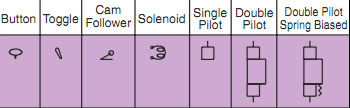
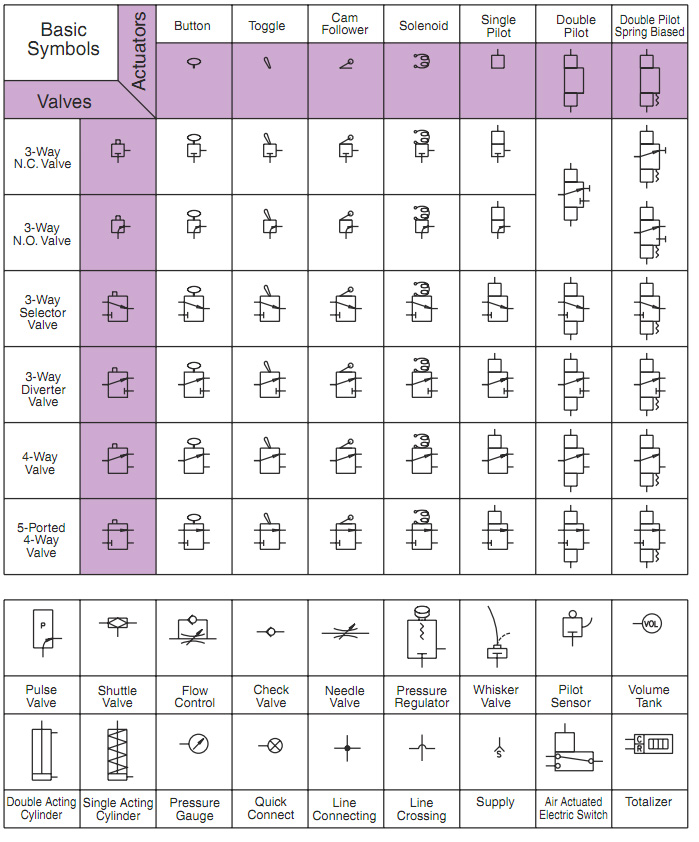
Directional valves comprise the largest portion of any air logic circuit. Complete directional valve symbols are created by combining the appropriate actuator and valve symbols found along the horizontal and vertical edges of the chart.
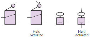
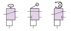
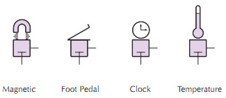
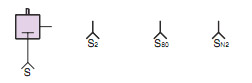
Seven of the most commonly used actuators are shown in the top bar. The designer is free to extend this list as may be required to suit a particular need.
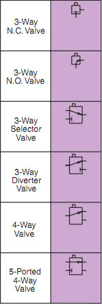
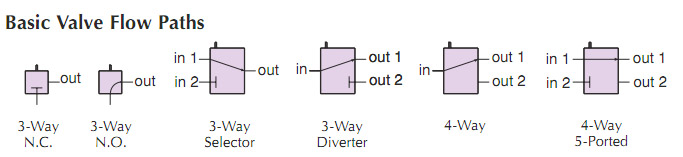
A close study of most air logic control circuits will reveal that there are only six basic valve functions commonly used. The symbols for these valve functions are shown in left graphic. These six basic valve symbols, when combined with the basic actuator symbols, comprise virtually all the directional valve symbols needed for air logic control.
Accessory components are designed for a specific purpose. The valves included in accessory components are basically flow devices that alter flow paths or signals, but do not generate signals by themselves.
Simplified symbols for accessory components are, for the most part, self explanatory and are shown at the bottom of page.
A brief review of the valves, their actuators, and how they combine into useful symbols, together with the examples contained in the following pages, will give the reader a valuable, time-saving method for drawing air logic control circuits.
|
Symbols created by combining valves and actuator

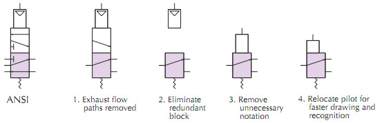
Derivation of Simplified Symbol from ANSI
Rules to help guide application:
8 simple rules in applying these air logic control symbols are as follows:
| 1. Symbols are always drawn in the valve’s normal unactuated position - not as held at the start of a cycle or as actuated. The flow direction or condition of the valve’s inlet is in its normal position. The symbol does not change, even if the valve is shown as actuated. To change the symbol would change the type of valve shown in the circuit. |
 |
2. Symbols do not show exhaust flow paths. Nearly all air logic circuit components exhaust to atmosphere, and exhaust flow paths are of little or no importance in understanding a pneumatic control circuit It is implied that all directional valves have their output either connected to their input or to atmosphere.
 |
3. In all symbols the valve is assumed to have a spring returning it to its normal condition unless otherwise shown. Remember, more than one type of actuator can be shown on opposite ends of the valve. |
| 4. Actuators are understood to push the flow path indicator when actuated, pushed or energized. Since the methods of actuating air logic valves are nearly limitless, the circuit designer may create additional actuator symbols to represent a special requirement. |
 |
| 5. Circuits should not be burdened with excessive supply lines. Supplies are shown at each component requiring one. Subscripts are used to identify different supplies, such as different pressures or medias. |
 |
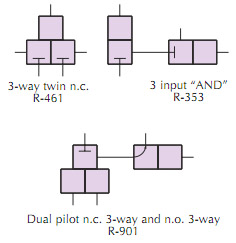
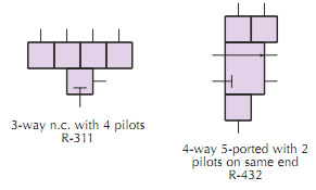
| 6. Special valve symbols may be constructed by the user or multiple symbols may be tied together and indicated as one component. |
7. In some specialized components more than one actuator (usually the same type) can be put on a valve. |
 |
 |
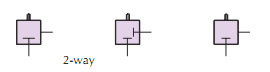
| 8. 2-way valves are seldom used in air logic circuits but on those occasions where a 2-way valve is needed the 3-way valve symbol can be used, with an appropriate notation as to its function in the circuit such as shown. |
 |
 |
The 3-way N.O. valve is the same regardless of how it is oriented or whether the outlet is to the right or left. Free orientation of symbols allows clarity in drawing circuits, minimizing design time spent on layout and in drawing. |
Versatile: It should be emphasized that the simplified symbols provided here are intended as a design aid, and may or may not be used to replace other formal symbologies for finished drawings. They are applicable to components of any manufacture as long as the component gives the same function.
Comparisons to Existing Symbols: It may be helpful to understand the useful simplicity of these new symbols by comparing them to existing symbology now in use.
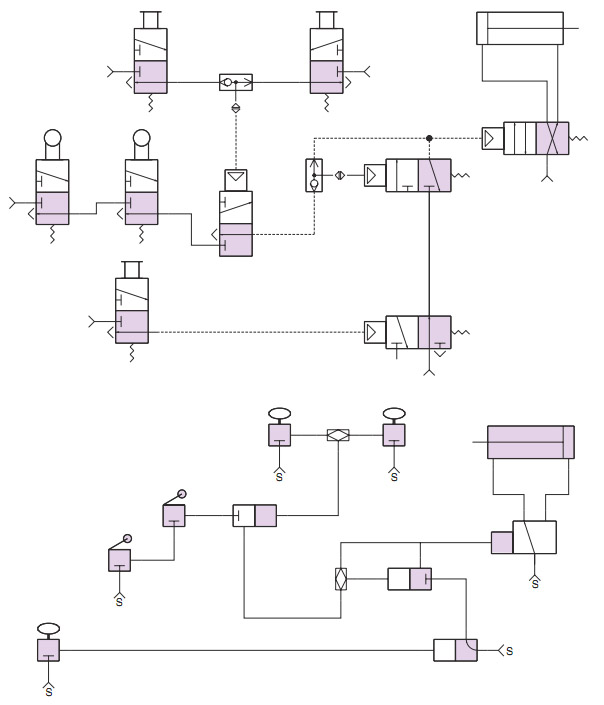
Shown below are air circuits using existing symbols for various types of valves, and the same circuits using the simplified symbols provided in this new method. The more complex symbols involve considerable time in drawing them. Many of the symbols are so closely alike as to cause confusion in understanding what is meant. Simplified symbols help eliminate this confusion.
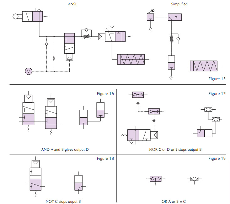
A few moments review of the comparisons will quickly reveal that the new simplified symbols provide an important aid for speed in designing new circuits. In air logic design where drawing time needs to be kept to a minimum, the new simplified symbols offer the designer new freedom to spend his time in the creative aspects of the task, rather than in the time-consuming details of excessive drawing.
Here is a complete chart of the basic valves, actuators, combinations and the auxiliary components used in pneumatic logic control circuitry.
Copyright 1985 Clippard Instrument Laboratory
Copyright 1985 Clippard Instrument Laboratory


