

How to Design Efficient Pneumatic Systems
Category:
Electronics have been a dominant control method for decades. But conditions sometimes exist that prohibit the use of electronic controls. For example, magnetic resonance imaging machines emit strong electromagnetic fields that are incompatible with strong ferrous metals and external electronic fields. Strong radio-frequency fields can interfere even with hard-wired electronic controls.
Furthermore, equipment operating in close proximity to explosives or fuels and other volatile fluids must be explosion-proof—a requirement that adds considerable bulk and expense to control components. These conditions may not be the norm, but any one of them can leave control system designers wondering what alternatives are available.
Designing Efficient Pneumatic Circuits
Pneumatic sequence controllers provide step-by-step system operation. Sequence valves and other components mount to the manifold subplates.
This is where pneumatic control provides a surprisingly wide array of solutions. Modular air-logic systems are often a good bet when a compact, economical unit is a must. They typically consist of a series of valves mounted onto standard manifold subplates.
For instance, compared with discrete air-valve control systems, a modular system provides:
• Proven, reliable design
• Lower component costs
• Simple plumbing and troubleshooting
• Lower air consumption
• No air locks
• A smaller total package
Compared to electrical-relay control, a modular system offers:
• An explosion-proof system with no danger of burnouts
• Lower power consumption
• Lower costs by eliminating solenoids and relays
• A single air supply
• No heat buildup
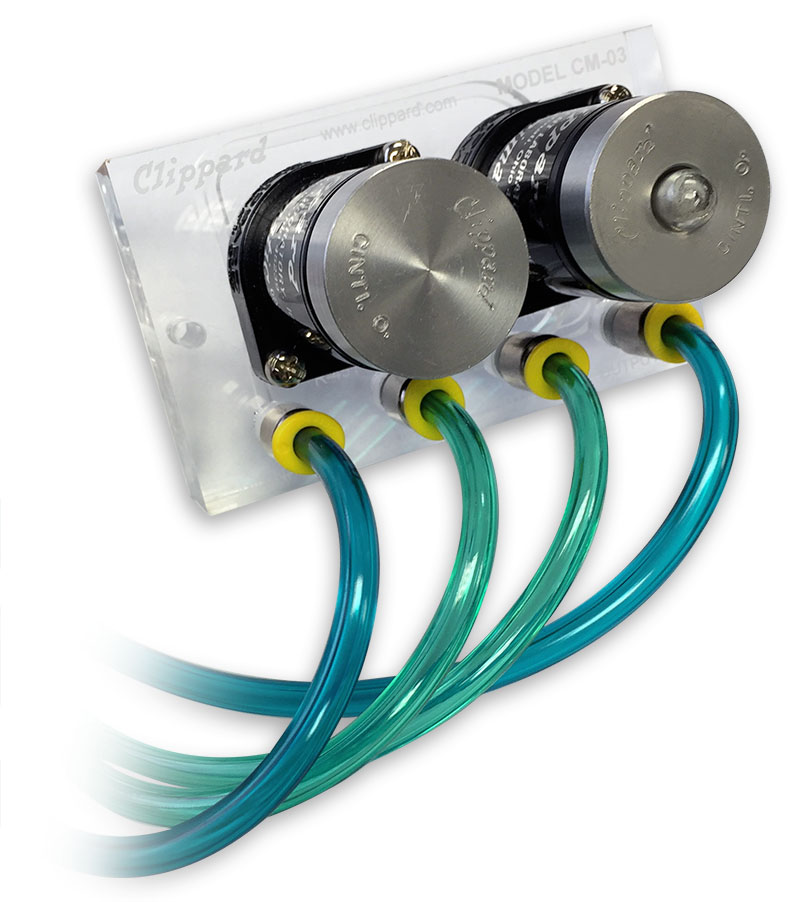
Only a few manufacturers offer modular, manifold-mounted pneumatic control systems. For instance, Clippard offers a pneumatic programmable controller—a sequential controller that provides step-by-step system operation. It consists of a clear acrylic manifold for mounting sequence valves and other such components in a compact, efficient package.
A selector valve gives the option of one-cycle operation or continuous cycling.
The system is designed to automatically generate feedback signals to initiate the next step when an operation finishes. Many types of sensors can generate feedback signals, including limit valves, proximity sensors, pressure sensors, Hall-effect switches, back-pressure cylinder sensors, and manual pushbuttons.
Feedback signals provide positive, safe operation. If no signals are sent (due to a component failure, missing or jammed parts, and so on), the sequence stops and an indicator pinpoints where to troubleshoot. Internal interlocks prevent out-of-sequence feedback signals.
A pneumatic output signal at each step actuates air-piloted devices, including power valves, hydraulic valves, pressure switches, and other components that may control air cylinders. The last sequence valve resets the system to repeat the cycle of operations.
Design Basics
Modular systems can contain just a few valves or dozens, with many built-in functions to permit a systematic approach to circuit design. As with any control system, it is essential to outline system requirements to save time and reduce the chances of missing a critical step.
Designers must also have a clear understanding both of the sequence of operations (including pressure, temperature, filtration, and other operating conditions) and the control requirements (including manual, automatic, start, stop, etc.). As a final check of circuit operation, consider proper actuation during all conceivable events. This includes startup, shut down, loss of air, panic stops in mid-cycle, restarts in mid-cycle, and control during any other event likely to occur.
Programming Guidelines
After defining the overall functions and requirements of a system, configure the system following some basic guidelines. First, label all components in the pneumatic circuit. At Clippard, we recommend labeling each cylinder with a letter of the alphabet, starting with A. The same holds for air motors and other controlled devices. Label the valve controlling the cylinder with the same letter.
System shutoff prevents accidental machine operation.
Label the pilot of the valve that extends the cylinder (or activates a device) with a plus symbol, and the pilot of the valve that retracts the cylinder (or turns off a device) with a minus symbol. Label the limit sensor the cylinder rod strikes with the letters LV (limit valve), the letter of the cylinder, and position of the sensor for extending or retracting. LVA+, for example, would mean the limit valve of an extended cylinder A.
Second, list in detail every sequence of operation. This includes the action or control that initiates a step, what function takes place during that step, and the limit sensor that ends the operation. Note what position all actuators are in for every step. An example of a simple two-cylinder sequence is shown in the accompanying table.
Third, select components for the control system. Modular systems offer great flexibility because users can incorporate multiple options when selecting sequence valves. For instance, in the "Two-cylinder sequence" example, five steps (extend and retract the two cylinders plus reset) require five sequence valves.
A basic valve could be used for each step, or you could choose valves with special features. For example, the first two steps could use a valve that provides a sequence reset lock if the start button is held down or if the limit valve LVA+ is locked down. Reset lock means the sequence will not reset to bypass the valve being actuated.
After choosing components, assemble fittings and modular valves into the subplate. Connect the air supply and lines from the limit valves and electrical connections from the Hall-effect sensors to the inlet connections. Finally, connect air lines from the outlet to the air pilots of the power valves.
Changing Operations
A shuttle valve to the pilot of a power valve lets a function actuate twice during a sequence.
Modular systems can be quickly tailored to meet specific requirements. Sequence conditions can be altered or adapted to the application by using different control modules. Here's a look at some common options.
Start options—If the application demands an input for each cycle of operations, use a pushbutton input signal and a sequence valve that provides a reset lock if the button is held actuated. If continuous cycling is required, use a selector or toggle valve at the input of the first step along with a valve that permits continuous cycle sequences. For applications requiring choosing between one cycle or continuous cycling, add a selector valve that determines the type of operation.
Manual jog—This control option lets users jog (step-by-step) through the machine sequences. One way to do this is to control air flow to the limit valves, with the jog control a pushbutton or spring-return selector. If held actuated, the sequence continues until released.
Another method for manual-jog control is to use a binary-trigger circuit that controls the input to the sequence circuit. This approach requires actuating the jog signal for each step. A delay-out valve resets the binary trigger when there are an odd number of sequence steps.
Two-cylinder sequence.
Reset—This control, when actuated, returns the sequence to the start position. Reset can also place power valves in a home position. A reset circuit should only be used when the control is in manual mode.
E-stop—Emergency-stop controls can halt system operations in several ways:
1. Stopping the sequence only
2. Stopping the sequence and relieving pressure
from the power valves
3. Stopping the sequence and activating reset controls
A latching mushroom-head button is commonly used for the emergency-stop control because it gives users a positive response when activated.
Jog control lets users manually step through machine operations. This option can be added by controlling flow to limit valves or adding a binary trigger.
System shutoff—These controls turn off the main air supply. This prevents harming people or product from accidental machine operation. If the system has large power valves, a piloted three-way main supply valve can control a specific machine section. When electrical circuits are part of the system, an air-piloted pressure switch ensures the system has electric power only if the air is on.
Multiple outputs—When two (or more) functions start with the same step, connect the output from that sequence step to both power valves.
Multiple functions—Functions that actuate twice during the sequence call for the system to connect a shuttle valve (OR function) to the pilot of the power valve.
Multiple inputs—When two functions actuate at the same time, a piloted three-way valve (AND function) ensures both functions are complete before the next step begins.
Delays—Applications requiring a delay before a step can use a delay-in module between the limit valve and the input to the step being delayed.
Backpressure sensing—Many air-cylinder applications cannot use mechanical limit valves for sensing because of physical interference, temperature extremes, or other conditions. A method called backpressure sensing indicates cylinder position without limit valves. For example, as a cylinder retracts, it creates a backpressure behind the piston. Restricting exhaust air at the control valve further increases pressure and slows return of the cylinder rod.
This backpressure holds the pilot down on a normally open (NO) three-way valve. When the cylinder fully returns, backpressure diminishes at the pilot port of the NO three-way valve, letting a spring shift the valve to send a pneumatic signal to the next step. If the system requires a delay, substitute a delay-out module for the three-way valve.
Original Article, March 2016
By Mike Kettering • Tech Sales Specialist • Clippard
Download Whitepaper (PDF)


